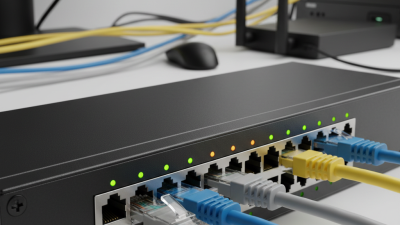
How to Choose the Right EZ RJ45 Connectors?
Choosing the right ez rj45 connectors is not merely a matter of matching a product photo. The connector must fit the cable, installation method, and network category. Cable diameter matters first. A slim Cat6 cable may not sit securely inside a connector designed for thicker Cat5e conductors. Solid and stranded conductors also require different contact designs.
Peter Jones, an Ethernet and cabling specialist, puts it plainly: “A connector is only as reliable as its termination, testing, and environment.” That principle is easy to overlook. Even a well-made ez rj45 connector can fail when the wires are uneven, the jacket is stripped too far, or the crimping tool applies weak pressure. Small details become visible under a tester.
Look closely at conductor compatibility, contact plating, boot design, shielding, and pass-through structure. Pass-through models can make wire sequencing easier, especially in crowded racks. However, they may create extra trimming work if the tool is poorly adjusted. Choose connectors certified for the cable category you actually use. Cat6 requirements should not be treated like Cat5e requirements.
There is no perfect connector for every job. A field technician may value speed, while a data-center installer may prioritize consistency and test results. That difference matters. Before ordering, test a sample with your exact cable and crimping tool. It may reveal an uncomfortable truth: the connector was not the problem. The installation process was.
Understanding EZ RJ45 Connector Design and Compatibility
How to Choose the Right EZ RJ45 Connectors?
Understanding EZ RJ45 Connector Design and Compatibility
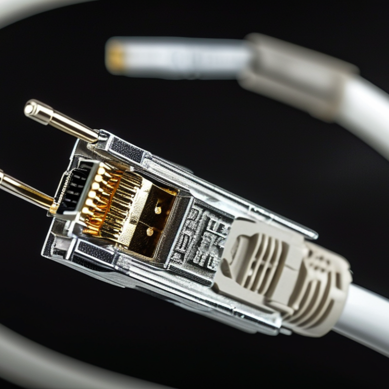
EZ RJ45 connectors allow the cable conductors to pass through the plug body. This design makes wire order easier to inspect before crimping. It can reduce mistakes during busy installations. After crimping, the exposed conductors are trimmed cleanly by a compatible crimping tool. The connector must match the tool’s cutting and crimping structure. Otherwise, the plug may look secure but fail electrical testing.
Compatibility depends on more than the connector category. Check the cable type, conductor size, insulation diameter, and jacket thickness. Solid-core and stranded cables often require different contact designs. Shielded cable also needs a matching shielded connector and proper grounding practice. A connector rated for a higher category cannot improve an inferior cable. It only supports the system when every component fits together.
In practical work, I would inspect the conductor order from the front before crimping. I once treated a tight fit as proof of compatibility, but the oversized jacket weakened the strain relief. That assumption needed reconsideration. Measure the cable first, then confirm the connector specifications and tool instructions.
Tips: Keep the cable jacket inside the plug’s rear section. Leave minimal untwisted wire near the contacts. Check that each conductor reaches the front evenly. After crimping, perform a continuity and wire-map test. Do not rely only on a visual inspection.
Identifying the Cable Type and Wiring Standard
Choosing the right EZ RJ45 connector starts with the cable, not the connector package. Identify the cable category, conductor type, diameter, and shielding. Cat5e, Cat6, and Cat6A cables can differ noticeably in insulation thickness. Cat6A often needs a larger connector opening. Solid conductors suit permanent links, while stranded conductors suit flexible patch cables. Mixing them can weaken the termination.
Check the wiring standard before inserting the wires. T568A and T568B both use all eight conductors, but the pair colors change. Use one standard at both ends. T568B is common in many commercial installations, while T568A may be required by a project specification. ISO/IEC 11801-1 and ANSI/TIA-568.2-D emphasize consistent pair arrangement and performance testing. A 2024 global data-center survey reported that 54% of operators experienced an outage during the previous three years. Poor cabling is not always the cause, but small installation errors can add risk. I have seen a connector pass a basic continuity test yet fail under higher-speed testing. That mistake is easy to underestimate.
Tips: Compare the connector’s conductor guide with the cable’s actual diameter. Keep each pair twisted as close to the contacts as possible. Do not force thick Cat6A cable into a narrow body. Confirm the color order twice. Test every finished link with a qualified cable analyzer, not only a wire map. My own process is still imperfect; I sometimes recheck the jacket fit after crimping, because visual confidence can be misleading.
| Selection Dimension | Cable or Wiring Condition | What to Check | Recommended Connector Match | Practical Verification |
|---|---|---|---|---|
| Connector Format | 8P8C modular plug with pass-through termination | Confirm that the plug is specifically designed for pass-through termination and that its load bar or wire manager accepts all eight conductors. | Use a compatible EZ-style pass-through plug rather than a standard closed-end plug. The crimp tool must support the same connector format. | Check the connector and tool instructions before crimping. |
| Cable Category | Category 5e | Designed for balanced twisted-pair Ethernet up to 100 MHz when the complete channel is correctly installed. | Choose a connector rated for at least Category 5e and matched to the cable conductor and insulation dimensions. | Do not assume a higher-category plug improves a lower-category cable. |
| Cable Category | Category 6 | Designed for frequencies up to 250 MHz. The cable may have larger conductors or a central separator. | Use a connector that accepts the cable diameter, conductor gauge, and any internal separator or spline arrangement. | Remove only the amount of jacket needed for termination and preserve pair twist as close to the plug as possible. |
| Cable Category | Category 6A | Designed for frequencies up to 500 MHz and commonly has a larger outside diameter than Category 5e or Category 6 cable. | Select a high-performance connector with a sufficiently large cable-entry range and suitable contact geometry. | Verify the connector’s stated category rating and maximum jacket diameter. |
| Cable Category | Category 8 | Designed for frequencies up to 2,000 MHz and normally requires carefully controlled components and installation practices. | Use only a connector explicitly rated for the required Category 8 application and cable construction. | Confirm the complete channel rating; a single lower-rated component can limit system performance. |
| Conductor Type | Solid conductors | Each conductor is a single copper wire. Horizontal in-wall Ethernet cable is commonly solid-conductor cable. | Choose a plug with contacts intended for solid conductors and a conductor-size range that matches the cable. | Inspect the terminated contacts to ensure they make reliable contact without damaging the conductor. |
| Conductor Type | Stranded conductors | Each conductor consists of multiple fine copper strands. Patch cables are commonly stranded for flexibility. | Use a plug designed for stranded conductors; solid-conductor plugs may not provide the intended contact performance. | Check the connector specification instead of selecting solely by cable category. |
| Conductor Gauge | Approximately 23–24 AWG | Common for many solid Ethernet cables, although actual sizes vary by cable design. | Select a connector whose conductor-entry range includes the measured wire diameter and insulation diameter. | Read the cable printing or measure the conductor before ordering connectors. |
| Conductor Gauge | Approximately 26–28 AWG | Common for many flexible stranded patch cables, but not universal. | Use a connector specifically supporting smaller conductors and the cable’s insulation thickness. | Confirm that the contacts reach the conductors after the plug is fully inserted. |
| Cable Shielding | Unshielded twisted pair (UTP) | The cable has no overall metallic shield or individual pair shields. | Use an unshielded modular plug with a compatible strain-relief boot if required. | Do not add a shielded plug to an unshielded cable as a substitute for a complete shielded system. |
| Cable Shielding | Shielded twisted pair (FTP, F/UTP, S/FTP, or similar) | The cable includes a foil, braid, or pair-level shielding structure that must be bonded through compatible hardware. | Use a shielded plug with a metal shield and strain-relief design suitable for the cable construction. | Ensure the shield can make continuous contact with the plug and the rest of the grounding path. |
| Cable Diameter | Small, standard, or large outside diameter | EZ-style plugs have a limited cable-entry and jacket-retention range. Category 6A and shielded cables are often larger. | Match the connector’s specified outer-jacket diameter range to the actual cable diameter. | Measure the jacket with calipers when the fit is uncertain; avoid forcing an oversized cable into the plug. |
| Wiring Standard | T568A | Pin order: 1 white/green, 2 green, 3 white/orange, 4 blue, 5 white/blue, 6 orange, 7 white/brown, 8 brown. | Arrange the conductors in the T568A order at both ends for a straight-through cable. | Use T568A consistently across the installation unless the existing system requires another standard. |
| Wiring Standard | T568B | Pin order: 1 white/orange, 2 orange, 3 white/green, 4 blue, 5 white/blue, 6 green, 7 white/brown, 8 brown. | Arrange the conductors in the T568B order at both ends for a straight-through cable. | T568B is widely used; consistency at both ends is more important than choosing A or B for a new straight-through cable. |
| Cable Type | Straight-through Ethernet cable | Both ends use the same wiring standard: T568A-to-T568A or T568B-to-T568B. | Terminate both plugs with identical conductor order and verify the pinout with a cable tester. | All eight conductors should map to the same pin number at both ends. |
| Cable Type | Crossover Ethernet cable | One end uses T568A and the other uses T568B, crossing the transmit and receive pairs. | Use only when the equipment or application specifically requires a crossover arrangement. | Modern network equipment often supports automatic pair correction, but the required wiring should still be confirmed. |
| Pair Arrangement | Correct pair grouping maintained | Each pair must remain together: pins 1–2, 3–6, 4–5, and 7–8 under the selected T568A or T568B scheme. | Use the connector’s wire guide to keep each twisted pair in the correct pair positions. | Never arrange conductors by color alone if doing so separates the members of a twisted pair. |
| Termination Quality | Conductors extend evenly through the plug | Pass-through conductors should reach the front of the plug in the correct order and be cut cleanly during crimping. | Use a compatible pass-through crimping tool with a properly aligned cutting mechanism. | Inspect the plug face, conductor order, contact penetration, and jacket position after crimping. |
| Final Test | Completed cable or installed link | Correct pinout alone does not confirm performance. Continuity, pair mapping, shorts, opens, and split pairs should be checked. | Use a wire mapper for basic verification and a qualified certification tester when a category-performance guarantee is required. | Test both ends and record failures before putting the cable into service. |
| Important Note | Connector specifications differ by construction | Conductor gauge, conductor type, insulation diameter, jacket diameter, shielding, and category rating are not universal across all plugs. | Choose the connector from the cable measurements and the connector datasheet, not from the RJ45 appearance alone. | Always verify the manufacturer’s dimensional and performance specifications for the exact connector model being used. |
Selecting the Correct Connector for Conductor Size
Choosing the correct conductor size is central to reliable EZ RJ45 connector termination. Copper cable commonly uses 22, 23, or 24 AWG solid conductors, while flexible patch cables often use 26 or 28 AWG stranded conductors. A connector designed for 23 AWG may grip poorly around a thinner 26 AWG conductor. That creates unstable contact pressure.
Check the connector’s stated conductor range, conductor type, insulation diameter, and cable jacket diameter. ANSI/TIA-568.2-D covers balanced twisted-pair cabling and separates permanent-link cable from flexible patch cords. ISO/IEC 11801-1 also defines a 100-meter channel, usually including a 90-meter permanent link and up to 10 meters of patch cords. These limits depend on correct components, not labels alone. Category ratings cannot fix a poor mechanical fit.
Use a connector with load bars or wire guides that match the cable geometry. Solid conductors should sit straight in each contact channel, without excessive force. Stranded conductors need contacts that can pierce insulation consistently without cutting the strands. Test the finished cable for wire mapping, resistance, and return loss. A visual inspection is not enough. In field work, installers sometimes focus on AWG and overlook insulation thickness. That is an easy mistake. Before crimping, compare the cable datasheet with the connector specification, then test a sample termination.
Checking Shielding, Boot, and Performance Requirements
How to Choose the Right EZ RJ45 Connectors?
When selecting EZ RJ45 connectors, check the cable structure before choosing the connector. Solid and stranded conductors need different contact designs. Cable diameter also matters. A tight fit can damage insulation or distort the conductors. In practical installations, I measure the jacket rather than trusting its printed category alone. Markings can fade. That small detail causes avoidable errors.
Shielding deserves careful attention in electrically noisy areas. Choose a shielded connector when the cable and network hardware support a continuous grounding path. The metal shell must contact the cable shield securely. Otherwise, the shield may offer little protection. Inspect the connection after crimping. Look for loose foil, uneven drain wire placement, or gaps around the jacket. These faults are easy to miss.
The boot should protect the latch and maintain a smooth bend near the plug. It should not press sharply against the cable. Select a boot that matches the cable diameter and installation space. For performance, verify the connector’s category rating, conductor compatibility, and contact quality. Test insertion loss, continuity, and wire mapping when the link is critical. A connector can look perfect and still fail under testing. I once treated visual inspection as enough; it was not. Performance requirements should guide the choice, not appearance alone.
Verifying Quality, Installation Method, and Network Fit
Choosing the right EZ RJ45 connector begins with quality, not convenience. Inspect the contacts, housing, and strain relief under bright light. Gold-plated contacts usually resist oxidation, but plating thickness still matters. A cheap-looking shell can weaken during repeated cable movement. Match the connector to the cable category, conductor size, and solid or stranded construction. Check published specifications, not only the package label.
Installation method affects signal stability as much as the connector itself. Pass-through designs simplify wire alignment, especially in a crowded cabinet. Cut conductors evenly, keep pair twists close to the contacts, and use a compatible crimping tool. Do not force an oversized cable into a narrow entry. After crimping, inspect the wire order and confirm that the jacket sits inside the strain-relief area. A continuity test helps, but it cannot reveal every performance problem. I once trusted a clean-looking termination that failed under movement. That mistake still matters.
Tips: Verify the wiring standard before termination. Test with a cable certifier when speed or bandwidth matters. Use short sample runs first. If the connector feels loose, stop and reassess. Connector fit also depends on the network. Consider category rating, shielding, patch-panel compatibility, and the installation environment. Outdoor or high-noise areas may require different protection. A connector can fit physically yet fail electrically. Record the cable type and test result for future maintenance.
How to Choose the Right EZ RJ45 Connectors
How to read the chart: Select a connector category that matches or exceeds the installed cable category. Cat 5e supports common 1 Gb/s networks, while Cat 6A is the practical choice for 10 Gb/s operation over a full 100 m channel.
- Verify quality: Check consistent contact plating, firm conductor retention, correct wire-management geometry, and compatibility with solid or stranded conductors.
- Confirm installation method: Use a pass-through design when easier conductor alignment and visual verification are important, but follow the connector manufacturer's approved termination procedure.
- Match the network: Choose the connector rating based on cable category, target speed, frequency, shielding type, and the required channel length.
Performance categories are based on commonly used ISO/IEC 11801 and ANSI/TIA-568 cabling specifications. Actual performance depends on the complete channel, including cable, connectors, patch panels, and installation quality.
Related Posts
-
What are RJ45 Connectors and Their Uses in Networking?
-
Why Are RJ45 Connectors Essential for Networking and Data Transmission?
-
Why Use RJ45 Crimpers for Your Networking Needs?
-
How to Choose the Best RJ45 Crimpers for Your Needs?
-
Why EZ RJ45 Connectors Are Essential for Your Networking Setup
-
Top 5 EZ RJ45 Connectors You Need to Know for 2025